Configuration
Note
The emonPi3 and emonTx6, by default, use 433.92 MHz for RF communication, rather than 433.00 MHz, to stay within the ISM regulated band. If you are using OpenEnergyMonitor emonTH2, emonPi2, emonTx4, or emonTx5 units you should update their firmware to support 433.92 MHz, or enable 433.00 MHz compatibility mode in the emonPi3/Tx6.
Through EmonCMS
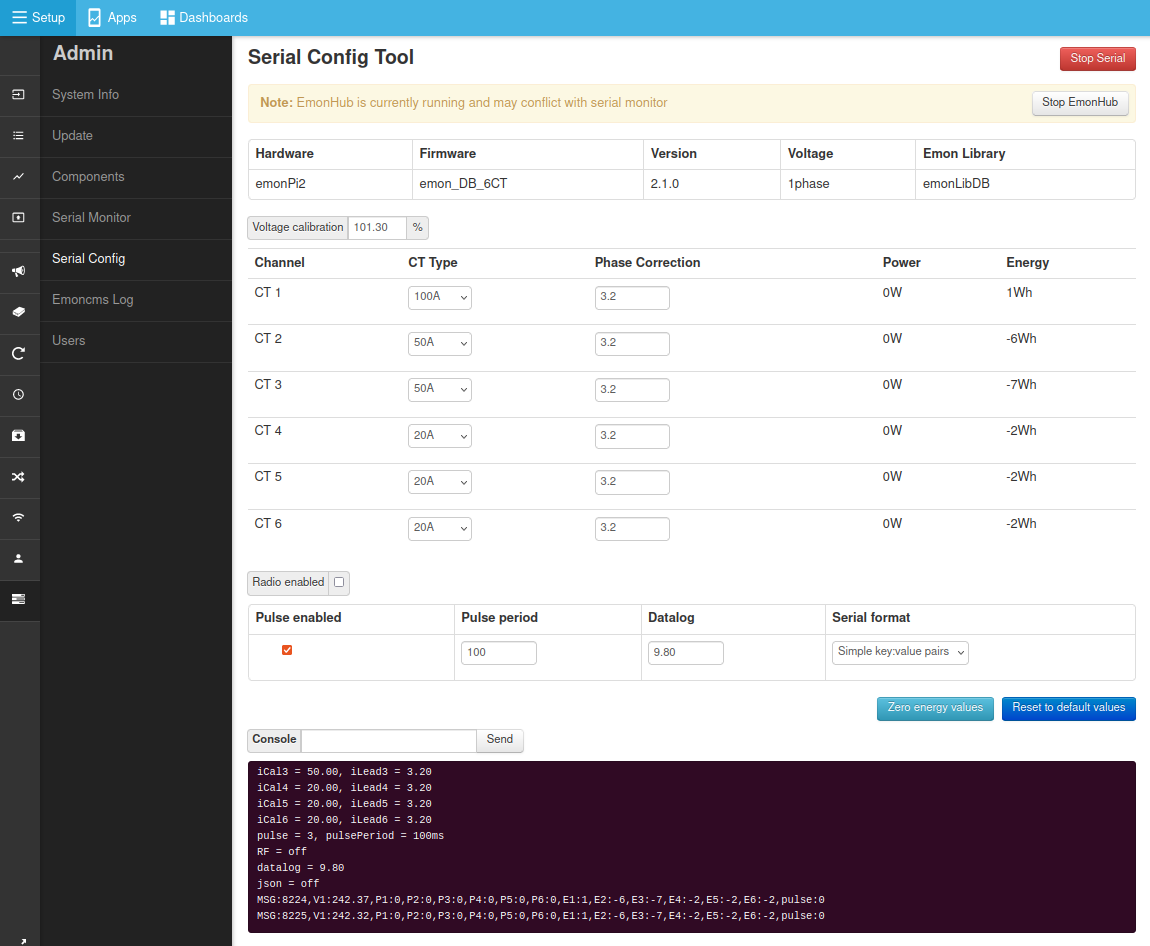
The emonPi3 is usually pre-configured in the shop as part of the order process but can be re-configured at any point using the Serial Config tool available from the emonPi3 local EmonCMS interface.
Navigate to
Setup > Admin > Serial ConfigClick on
Stop EmonHubto temporarily stop the EmonHub service while we perform calibration.Select serial port
/dev/ttyAMA0and clickConnect.After a couple of seconds the emonPi3 will print out its current configuration which will populate the interface (if it does not do this type
land clickSendto reload the calibration details from the emonPi3 measurement board).Adjust any settings you need to change.
Click on
Save Changesto ensure that the new configuration is recorded such that it persists when you power cycle the board.When finished, click on
Stop Serialto disconnect the serial configuration tool and thenStart EmonHubto restart the EmonHub service.
Directly via serial
It is possible to configure the emonPi3/Tx6 directly through the USB serial port or UART using minicom or other similar tool. When using a UART, the settings are 115200, 8N1, \r\n line ending.
The following table details the available commands and their function.
Command |
Description |
|---|---|
? |
Show help text |
emonlock |
Lock the configuration interface |
emonunlock |
Unlock the configuration interface |
a<n> |
Set the assumed RMS voltage as integer (when no AC voltage detected) |
b |
Backup configuration to serial |
c<n> |
Log to serial output |
d<x.x> |
Set data log period in seconds |
e |
Enter bootloader mode for firmware updates |
f<n> |
Set line frequency in Hz |
g<n> |
Set network group for RF communication (default = 210) |
h |
Safe Raspberry Pi power off countdown (will not remove power) |
i<x> <y> <i.i> |
Auto calibration |
j<n> |
JSON serial format |
k<x> <a> <y.y> <z.z> <v1> <v2> |
Configure an analog input (voltage or current) |
l |
List current settings (displays all configuration) |
ls |
List saved settings (displays all configuration) |
lh |
List current settings (displays all configuration), human readable |
lhs |
List saved settings (displays all configuration), human readable |
m<v> <w> <x> <y> <z> |
Configure a OneWire/pulse input |
n<n> |
Set node ID [1..60] |
o |
OneWire configuration |
p<n> |
Set the RF power level (0-31). Transmitter may be damaged for values greater than 25 when no antenna is installed. |
q |
Reset the system (confirmation required) |
r |
Restore default settings (unsaved changes will be lost) |
rs |
Restore saved settings (unsaved changes will be lost) |
s |
Save settings to NVM (non-volatile memory) |
t |
Trigger report on next cycle (force immediate data transmission) |
u |
Save accumulator values to NVM |
v |
Show firmware and board information |
w<n> |
RF module active |
x<n> |
433 MHz RF frequency compatibility |
ye |
Set energy accumulator |
yp |
Set pulse accumulator |
z |
Zero energy/pulse accumulators (reset Wh/pulse counters) |
Locking and unlocking the configuration
To protect against accidental changes, the configuration interface can be locked against changes. Read only commands are still available when locked.
EmonHub Node Decoder Configuration
The emonTx6 transmits data via RF that needs to be decoded by EmonHub. The node decoder configuration defines how the raw data packets are interpreted. Configuration depends on whether the emonTx6 is operating in single-phase or three-phase mode.
Single-Phase Mode
The decoder configuration for node 20 (main CT1-6 channels) in single-phase mode is:
[[20]]
nodename = emonTx6_20
[[[rx]]]
names =     MSG, Vrms1, Vrms2, Vrms3, P1, P2, P3, P4, P5, P6, E1, E2, E3, E4, E5, E6
datacodes = L, h, h, h, h, h, h, h, h, h, l, l, l, l, l, l
scales =    1.0, 0.01, 0.01, 0.01, 1.0, 1.0, 1.0, 1.0, 1.0, 1.0, 1.0, 1.0, 1.0, 1.0, 1.0, 1.0
units =     n, V, V, V, W, W, W, W, W, W, Wh, Wh, Wh, Wh, Wh, Wh
Data fields:
MSG: Message counterVrms1: Single RMS voltage (scaled by 0.01)Vrms2: Always 0Vrms3: Always 0P1-P6: Real power for CT channels 1-6 (watts)E1-E6: Energy accumulator for CT channels 1-6 (watt-hours)
In single-phase mode, Vrms2 and Vrms3 will always read as 0.
Three-Phase Mode
When all three voltage channels (V1, V2, V3) are active on the emonTx6, it operates in three-phase mode and transmits three-phase voltage readings along with power and energy data.
The decoder configuration for node 20 (main CT1-6 channels) in three-phase mode is:
[[20]]
nodename = emonTx6_20
[[[rx]]]
names =     MSG, Vrms1, Vrms2, Vrms3, P1, P2, P3, P4, P5, P6, E1, E2, E3, E4, E5, E6
datacodes = L, h, h, h, h, h, h, h, h, h, l, l, l, l, l, l
scales =    1.0, 0.01, 0.01, 0.01, 1.0, 1.0, 1.0, 1.0, 1.0, 1.0, 1.0, 1.0, 1.0, 1.0, 1.0, 1.0
units =     n, V, V, V, W, W, W, W, W, W, Wh, Wh, Wh, Wh, Wh, Wh
Data fields:
MSG: Message counterVrms1, Vrms2, Vrms3: Three-phase RMS voltages (scaled by 0.01)P1-P6: Real power for CT channels 1-6 (watts)E1-E6: Energy accumulator for CT channels 1-6 (watt-hours)
Additional Nodes
Both single-phase and three-phase modes use additional nodes for supplementary data:
Node N+1: Temperature, pulse, and analog data (node 21 if N=20)
Node N+2: Extended CT channels 7-12 (node 22 if N=20)
Configuration Steps
Determine your emonTx6’s operating mode by checking which voltage channels are active (use the
lcommand in serial configuration).Select the appropriate decoder configuration above (single-phase or three-phase).
Adjust the node number
[[20]]to match your emonTx6’s configured node ID.Add the configuration to your
emonhub.conffile in the appropriate section.